- Home
- /
- Ancillary Products
- /
- Pump Protectors

All centrifugal pumps, both sealless (canned motor or magnetic drive) and mechanical seal, will fail if they are run dry, so it is critical to invest in an inexpensive and simple technology such as a power monitor which will immediately detect low power draw caused by loss of flow to the suction of the pump and immediately shut the pump down before any major damage can occur. Power monitors can also be set to shut pumps down if it detects high power draw which can be caused by running the pump off the end of the curve or by mechanical contact or rubbing of some kind. The cost of a power monitor is cheap insurance to make sure that your Magnatex pumps, mechanical seal pumps or other rotating equipment will run trouble free for many years to come.
For Quality Management System:
(Applicable for IAS Accredited Certification)


ISO 9001: Registered
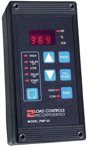
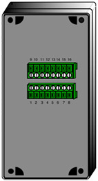
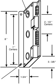
Mounting
Wiring is done to unpluggable terminal strips on the rear of the unit. There are three ways to mount:
Voltage
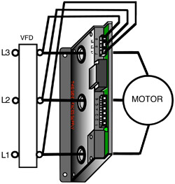
120 volts AC is taken from two of the phases. If the motor starter already has a 120-volt control transformer with 10VA of free capacity, it can be used. Otherwise, install a separate transformer. It is okay if the secondary is grounded. BE SURE TO NOTE WHICH TWO PHASES SUPPLY THE TRANSFORMER.
In a 120/208V three-phase system, the 120V MUST come from a transformer connected to two of the phases. The 120V phase to ground voltage cannot be used.
Current
The current signal is taken from the REMAINING phase. This current sample passes through the Range Finder Toroid. It is VERY IMPORTANT that the current signal comes from the phase that IS NOT supplying the 120V control transformer. Be extra careful when the machine has reversing starters or multi-speed windings. If a wrong phase is used, the control will either:

Connect with a Magnatex representative to learn more about our products or to request a quote.
Contact Us
Full scle Capacity at 460 Volts
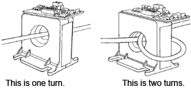
The Range Finder Toroid has six motor size choices. Select one that is equal or larger than your motor. This will leave some headroom.
Multipilers
For nominal voltages other than 460 volts, multiply 460V full scale by:
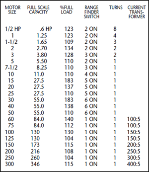
Current Transform

For motors sizes or capacities not in table:
%Full Load = F u l l S c a l e C a p a c i t y x 100 Your Motor Size
For Motors Less Than 5 HP
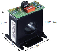
Take more "turns" of the leg through the Toroid. Each time the wire passes through the Toroid is a "turn".
For Motors Greater Than 50 HP
A Current Transformer is used to reduce the primary current. The 5-amp secondary passes through the Toroid.
Caution
When current is flowing through the primary of the external current transformer, always have a wire between the two brass Terminals on the CT.
If they are left open, dangerous and destructive voltages can develop.
Hooking up the Reset
Control can be reset three ways:
Remote Reset
Automatic Reset
Jumper Terminal 4 or 5 to Terminal 6
The terminals for Reset generate a small amount of current (8-12 milliamps). To reset, you just need to connect the terminal to the circuit common (Terminal 6).
The switches or relays that you use must be suitable for low current (Gold flashed contacts, Reed Relays, Mercury Switches).
4-20 MILLIAMP ANALOG OUTPUT
The Analog Output is directly proportional to Full Scale capacity. It is always active. 500 ohm maximum connected impedance.
Terminal 2 - 4-20mA - Positive
Terminal 3 - 4-20mA - Negative
Use twisted pair or in noisy environments, use shielded cable. Ground shield at other end.
Use the Full Scale capacity from the chart to scale external meter, chart recorders or computers.
THE PMP-25 POWERS THE 4-20MA SIGNAL DON'T USE AN EXTERNAL DC POWER SUPPLY.
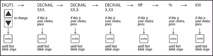
TO SET FULL SCALE
 Scalecycles through the choices shown below and blinks slowly for each choice. Each press of
Scalemoves you to the next choice
Scalecycles through the choices shown below and blinks slowly for each choice. Each press of
Scalemoves you to the next choiceFRONT PANEL SET-UP TIPS
1.None of the settings will be changed until you hold down  and the fast blinking stops.
2.Five seconds after you have pressed a button, the control will return to normal operation.
3.If you hold down the![]() digits will continue to change.
digits will continue to change.
4.You only need to do when you install the PMP-25 (or if you change the hook-up).
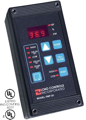
ADJUSTMENTS
SET POINT - HIGH: The HIGH relay will switch when the load is above the HIGH.
SET POINT - LOW: The LOW relay will switch when the load is below the LOW.
Start-up Timer
The Start-up Timer bypasses the Control during motor startup to avoid false trips because of current inrush. For convenience, the TIMING BEGINS WHEN THE MOTOR STARTS. The Start-up LED stays lit until the start-up period is over.
The start-up time should be:
Delay Timers
To avoid nuisance trips from short overloads, Delay Timers bypass the Control for the selected time. The relays won't trip until the time is exceeded. If the trip condition goes away before the time is up, the timer resets to zero.
TO VIEW AND CHANGE THE SET POINTS AND DELAY TIMES
![]() cycles through the choices. The LED for each choice will turn ON.To change a setting, use
cycles through the choices. The LED for each choice will turn ON.To change a setting, use ![]()
Press ENTER until quick blinking stops to store your new choice.
After 5 seconds if you haven't pressed any buttons, control will return to normal operation.
ADJUSTMENT TIPS FOR CENTRIFUGAL PUMPS From Pump Curves
Use the recommended minimum and maximum flows and horsepower for your initial set points.
Actual Operation
Low Trip - Run the pump with the OUTLET valves closed. This is the minimum flow. Set the low trip about here. High Trip - Run the pump with all valves wide open. This is the maximum flow. Set the high trip about here.
V-Series Control System The UPC and V-Series Load Controls Protect equipment driven by Variable Speed Motor Drives
V-Series Load Controls and UPC Power Cells are used together to protect equipment in Variable Speed motor drive applications. The UPC monitors motor power and sends a 0-10V signal to the V-Series Load Control. Each Load Control has adjustable set points and relay outputs. The set point configuration differs depending on the application and is called out by a specific model number.
The UPC measures True Power ( Watts ) on the output side of AC or DC motor drives and is field scaleable from small motors to 150 HP. Response time is field adjustable from 500 ms to 12 Sec. The UPC-FR has a fast Response time field adjustable from 50 ms to 1.2 Sec.
The V-Series Load Controls read the measured load on a digital display in either HP, KW or % Load. The meter also reads the set point and delay settings during setup. A HIGH trip set point will trip an output form C relay on an increase in load and a LOW trip set point will trip an output form C relay on a loss of load. Reset can be done manually, remotely with a switch or automatically using jumpers on the resets. A 4-20ma analog output is also provided.
Notes:
*The 0-10V signal (terminals 2 and 3) from the UPC power cell wires to the V-Series Load Control (terminals 8 and 7). A shielded signal wire should be used and the shield connected to GROUND at one end. *Relay outputs on the V-Series Load Control are shown with POWER ON and NOT TRIPPED. The trip condition is the shelf state.
UPC/UPC-FR
V-Series Back View
V-Series Control
UPC / UPS-FR

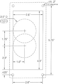
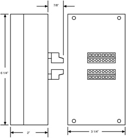
The Mounting Template ships with the V-series control and is used to mark hole punches for mounting on the outside of a panel door or raceway. To mount behind panel door or raceway use template to make a rectangular cut out and the BEZEL is used. Ask for the BEZEL kit when ordering ( no charge ). Gaskets are provided for both mounting options to maintain NEMA 4 integrity.
The OUTLET BOX ADAPTER is used for a surface or backplane mount. This adapter will adapt to an OUTLET BOX so the V-Series connectors are spaced off the backplane of the panel. Ask for OUTLET BOX ADAPTER when ordering (no charge). Gaskets are provided.