Regenerative Turbine Pump, Low NPSH, Low Flow-High Head

For Quality Management System:
(Applicable for IAS Accredited Certification)

ISO logo
ISO logo

ISO 9001: Registered

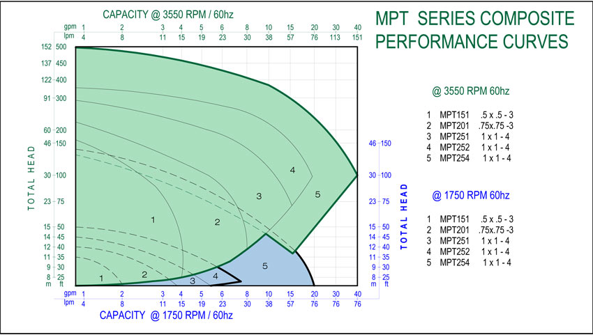
MPT Series magnetically driven, sealless, regenerative turbine vane pumps are designed specifically for low NPSH, low flow at high heads. The MPT Series features close coupled construction similar to the MP Series, but uses a regenerative turbine vane impeller. This design provides better pump hydraulics at low flow rates and low NPSHa conditions.

MPT Series Pumps

Magnetic Drive Pumps

  • Mag drive sealless pumps eliminate the need for expensive mechanical seals; eliminating costly shutdowns and repairs, which helps reduce "Reportable Release" issues.
  • No maintenance intensive mechanical seals required. No seal flush or complex and expensive seal pot systems to monitor or maintain.
  • Standard SiC-X bearing system for enhanced dry running capability
  • Straddle-mounted, inner magnet system, with bearings on both sides of the magnet, which reduces shaft and bearing loads when compared to our competitors' overhung, cantilevered inner magnet designs
  • Slip-fit construction that allows easy on-site maintenance, with no special tools or fixtures required
  • Close coupled configuration eliminates coupling and motor alignment issues
  • Handles toxic, noxious and corrosive liquids for leak-free pumping with increased safety to plant personnel and the environment
  • Excellent for pumping entrained gases
  • Excellent for low NPSH applications

Materials of Construction

  • 316 SS


Connect with a Magnatex representative to learn more about our products or to request a quote.

Contact Us

MAGNATEX® MPT Series Specifications

Maximum Flow 40 GPM
Maximum Head 440 FT
Liquid Temperature -22° F to 445° F
Maximum Power 20 HP
Connections NPT with Optional Flanges
Bearings SiC-X
Working Pressure 232 psig
Impeller Turbine Vane
Speeds Up to 3550 rpm
Magnets Neodymium or Samarium Cobalt
Motor NEMA or IEC Frame Mounted

How a Regenerative Turbine Pump Works
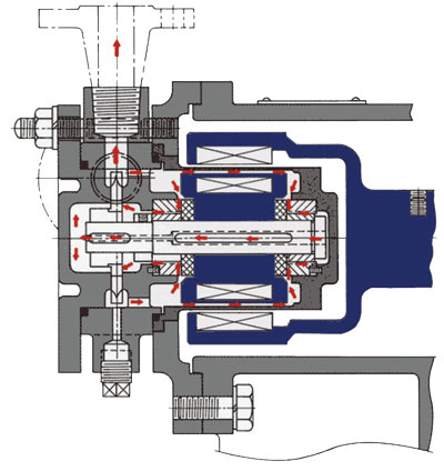
  • The unusual regenerative turbine impeller design involves a large number of blades machined into the periphery of the impeller.
  • Blades are on both sides of the centerline to limit axial thrust, which hydraulically centers the impeller during operation.
  • Instead of the liquid entering the impeller at the shaft centerline and exiting at the impeller periphery, liquid enters a regenerative turbine pump in the vicinity of the impeller OD. After acceleration around the pump casing it discharges through a port in the same plane as the suction.
  • There is considerable debate about the fluid dynamics involved in regenerative turbine pumps, but the consensus of expert opinion is that liquid entering the impeller blade is accelerated radially and tangentially in the direction of rotation. Liquid moving outward toward the casing is reflected back onto the next impeller blade where it is further accelerated. This process is repeated many times until the liquid exits the discharge port.
  • The clearances between the impeller and casing and between the inlet and outlet are smaller to minimize backflow in the discharge segment of the casing.
  • Regenerative turbine pumps develop much more head for the impeller diameter and speed of rotation when compared to a typical centrifugal pump.
  • Because of the special impeller design, regenerative turbine pumps are excellent for low NPSH applications.